The TikZ and PGF Packages
Manual for version 3.1.9a
Libraries
63 Three Point Perspective Drawing Library
by Max Snippe
TikZ Library perspective 
\usetikzlibrary{perspective} %
LaTeX
and plain
TeX
\usetikzlibrary[perspective] % ConTeXt
This library provides tools for perspective drawing with one, two,
or three vanishing points.
63.1 Coordinate Systems
Coordinate system three point perspective 
The three point perspective coordinate system is very similar to the xyz coordinate system, save that it will display the provided coordinates with a perspective projection.
/tikz/cs/x=⟨number⟩ (no default, initially 0)
The \(x\) component of the coordinate. Should be given without unit.
/tikz/cs/y=⟨number⟩ (no default, initially 0)
Same as x.
/tikz/cs/z=⟨number⟩ (no default, initially 0)
Same as x.
Coordinate system tpp 
The tpp coordinate system is an alias for the three point perspective coordinate system.
63.2 Setting the view
/tikz/3d view={⟨azimuth⟩}{⟨elevation⟩} (default {-30}{15}) 
With the 3d view option, the projection of the 3D coordinates on the 2D page is defined. It is determined by rotating the coordinate system by \(-\meta {azimuth}\) around the \(z\)-axis, and by ⟨elevation⟩ around the (new) \(x\)-axis, as shown below.
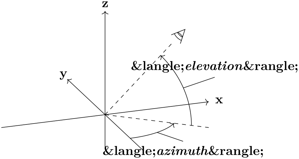
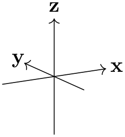
For example, when both ⟨azimuth⟩ and ⟨elevation⟩ are 0\(^\circ \), \(+z\) will be pointing upward, and \(+x\) will be pointing right. The default is as shown below.
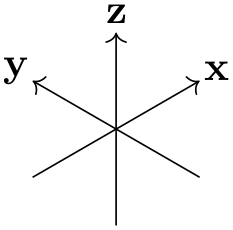
/tikz/isometric view(style, no value) 
A special kind of 3d view is isometric, which can be set with the isometric view style. It simply sets 3d view={-45}{35.26}. The value for ⟨elevation⟩ is determined with \(\arctan (1/\sqrt {2})\). In isometric projection the angle between any pair of axes is 120\(^\circ \), as shown below.
63.3 Defining the perspective
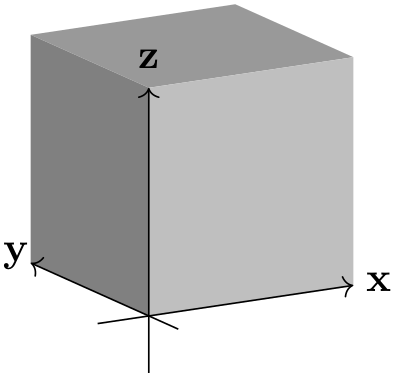
In this section, the following example cuboid will be used with various scaling. As a reference, the axes will be shown too, without perspective projection.
                \usetikzlibrary {perspective}

                \newcommand\simplecuboid[3]{%

                  \fill[gray!80!white] (tpp cs:x=0,y=0,z=#3)

                    --
                (tpp cs:x=0,y=#2,z=#3)

                    --
                (tpp cs:x=#1,y=#2,z=#3)

                    --
                (tpp cs:x=#1,y=0,z=#3) --
                cycle;

                  \fill[gray]  (tpp cs:x=0,y=0,z=0)

                    --
                (tpp cs:x=0,y=0,z=#3)

                    --
                (tpp cs:x=0,y=#2,z=#3)

                    --
                (tpp cs:x=0,y=#2,z=0) --
                cycle;

                  \fill[gray!50!white] (tpp cs:x=0,y=0,z=0)

                    --
                (tpp cs:x=0,y=0,z=#3)

                    --
                (tpp cs:x=#1,y=0,z=#3)

                    --
                (tpp cs:x=#1,y=0,z=0) --
                cycle;}

                \newcommand{\simpleaxes}[3]{%

                  \draw[->] (-0.5,0,0) --
                (#1,0,0) node[pos=1.1]{x};

                  \draw[->] (0,-0.5,0) --
                (0,#2,0) node[pos=1.1]{y};

                  \draw[->] (0,0,-0.5) --
                (0,0,#3) node[pos=1.1]{z};}


                \begin{tikzpicture}[3d view]

                  \simplecuboid{2}{2}{2}

                  \simpleaxes{2}{2}{2}

                \end{tikzpicture}
/tikz/perspective=⟨vanishing points⟩ (default p={(10,0,0)},q={(0,10,0)},r={(0,0,20)}) 
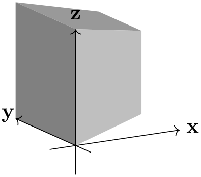
The ‘strength’ of the perspective can be determined by setting the location of the vanishing points. The default values have a stronger perspective towards \(x\) and \(y\) than towards \(z\), as shown below.
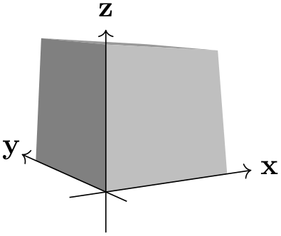
                  \usetikzlibrary {perspective}

                  \begin{tikzpicture}[3d view,perspective]

                    \simplecuboid{2}{2}{2}

                    \simpleaxes{2}{2}{2}

                  \end{tikzpicture}
From this example it also shows that the maximum dimensions of the cuboid are no longer 2 by 2 by 2. This is inherent to the perspective projection.
/tikz/perspective/p={⟨x,y,z⟩} (no default, initially (0,0,0)) 
The location of the vanishing point that determines the ‘strength’ of the perspective in \(x\)-direction can be set with the p key.
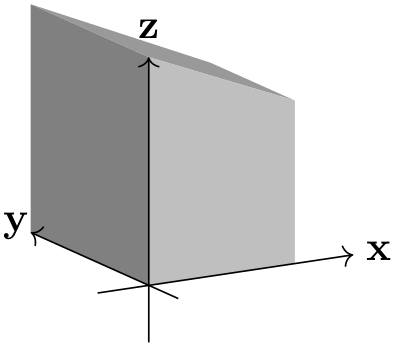
                    \usetikzlibrary {perspective}

                    \begin{tikzpicture}[

                      3d view,

                      perspective={

                          p
                      = {(5,0,0)}}]

                      \simplecuboid{2}{2}{2}

                      \simpleaxes{2}{2}{2}

                    \end{tikzpicture}
Note also that when only p is provided, the perspective in \(y\) and \(z\) direction is turned off.
To turn off the perspective in \(x\)-direction, one must set the \(x\) component of p to 0 (e.g. p={(0,a,b)}, where a and b can be any number and will be ignored). Or one can provide q and r and omit p.
By changing the \(y\) and \(z\) components of p, one can achieve various effects.
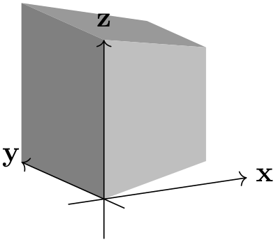
                    \usetikzlibrary {perspective}

                    \begin{tikzpicture}[

                      3d view,

                      perspective={

                          p
                      = {(5,0,1)}}]

                      \simplecuboid{2}{2}{2}

                      \simpleaxes{2}{2}{2}

                    \end{tikzpicture}
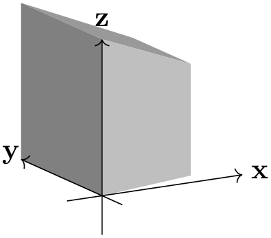
                    \usetikzlibrary {perspective}

                    \begin{tikzpicture}[

                      3d view,

                      perspective={

                          p
                      = {(5,1,0)}}]

                      \simplecuboid{2}{2}{2}

                      \simpleaxes{2}{2}{2}

                    \end{tikzpicture}
                    \usetikzlibrary {perspective}

                    \begin{tikzpicture}[

                      3d view,

                      perspective={

                          p
                      = {(5,1,1)}}]

                      \simplecuboid{2}{2}{2}

                      \simpleaxes{2}{2}{2}

                    \end{tikzpicture}
/tikz/perspective/q={⟨x,y,z⟩} (no default, initially (0,0,0)) 
Similar to p, but can be turned off by setting its \(y\) component to 0.
                    \usetikzlibrary {perspective}

                    \begin{tikzpicture}[

                      3d view,

                      perspective={

                          q
                      = {(0,5,0)}}]

                      \simplecuboid{2}{2}{2}

                      \simpleaxes{2}{2}{2}

                    \end{tikzpicture}
/tikz/perspective/r={⟨x,y,z⟩} (no default, initially (0,0,0)) 
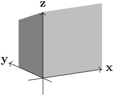
Similar to p, but can be turned off by setting its \(z\) component to 0.
                    \usetikzlibrary {perspective}

                    \begin{tikzpicture}[

                      3d view,

                      perspective={

                          r
                      = {(0,0,5)}}]

                      \simplecuboid{2}{2}{2}

                      \simpleaxes{2}{2}{2}

                    \end{tikzpicture}
63.4 Shortcomings
Currently a number of things are not working, mostly due to the fact that PGF uses a 2D coordinate system underwater, and perspective projection is a non-linear affine transformation which needs to be aware of all three coordinates. These three coordinates are currently lost when processing a 3D coordinate. The issues include, but possibly are not limited to:
-
• Keys like shift, xshift, yshift are not working
-
• Keys like rotate around x, rotate around y, and rotate around z are not working
-
• Units are not working
-
• Most keys from the 3d library are unsupported, e.g. all the canvas is .. plane keys.
63.5 Examples
An r that lies ‘below’ your drawing can mimic a macro effect.
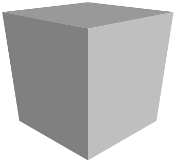
                \usetikzlibrary {perspective}

                \begin{tikzpicture}[

                  isometric view,

                  perspective={

                      p
                  = {(8,0,0)},

                      q
                  = {(0,8,0)},

                      r
                  = {(0,0,-8)}}]


                  \simplecuboid{2}{2}{2}


                \end{tikzpicture}
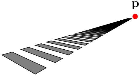
A peculiar phenomenon inherent to perspective drawing, is that however great your coordinate will become in the direction of the vanishing point, it will never reach it.
                \usetikzlibrary {perspective}

                \begin{tikzpicture}[

                  isometric view,

                  perspective={

                      p
                  = {(4,0,0)},

                      q
                  = {(0,4,0)}}]


                    \node[fill=red,circle,inner sep=1.5pt,label=above:p] at
                (4,0,0){};


                    \foreach \i in
                {0,...,100}{

                      \filldraw[fill =
                gray] (tpp cs:x=\i,y=0,z=0)

                        --
                (tpp cs:x=\i+0.5,y=0,z=0)

                        --
                (tpp cs:x=\i+0.5,y=2,z=0)

                        --
                (tpp cs:x=\i,y=2,z=0)

                        --
                cycle;}

                \end{tikzpicture}
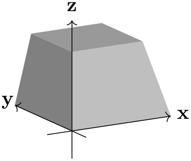
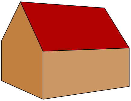
Even for simple examples, the added perspective might add another ‘dimension’ to your drawing. In this case, two vanishing points give a more intuitive result then three would.
                \usetikzlibrary {perspective}

                \begin{tikzpicture}[

                  scale=0.7,

                  3d view,

                  perspective={

                      p
                  = {(20,0,0)},

                      q
                  = {(0,20,0)}}]


                  \filldraw[fill=brown] (tpp cs:x=0,y=0,z=0)

                    --
                (tpp cs:x=0,y=4,z=0)

                    --
                (tpp cs:x=0,y=4,z=2)

                    --
                (tpp cs:x=0,y=2,z=4)

                    --
                (tpp cs:x=0,y=0,z=2) --
                cycle;

                  \filldraw[fill=red!70!black] (tpp cs:x=0,y=0,z=2)

                    --
                (tpp cs:x=5,y=0,z=2)

                    --
                (tpp cs:x=5,y=2,z=4)

                    --
                (tpp cs:x=0,y=2,z=4) --
                cycle;

                  \filldraw[fill=brown!80!white] (tpp cs:x=0,y=0,z=0)

                    --
                (tpp cs:x=0,y=0,z=2)

                    --
                (tpp cs:x=5,y=0,z=2)

                    --
                (tpp cs:x=5,y=0,z=0) --
                cycle;

                \end{tikzpicture}
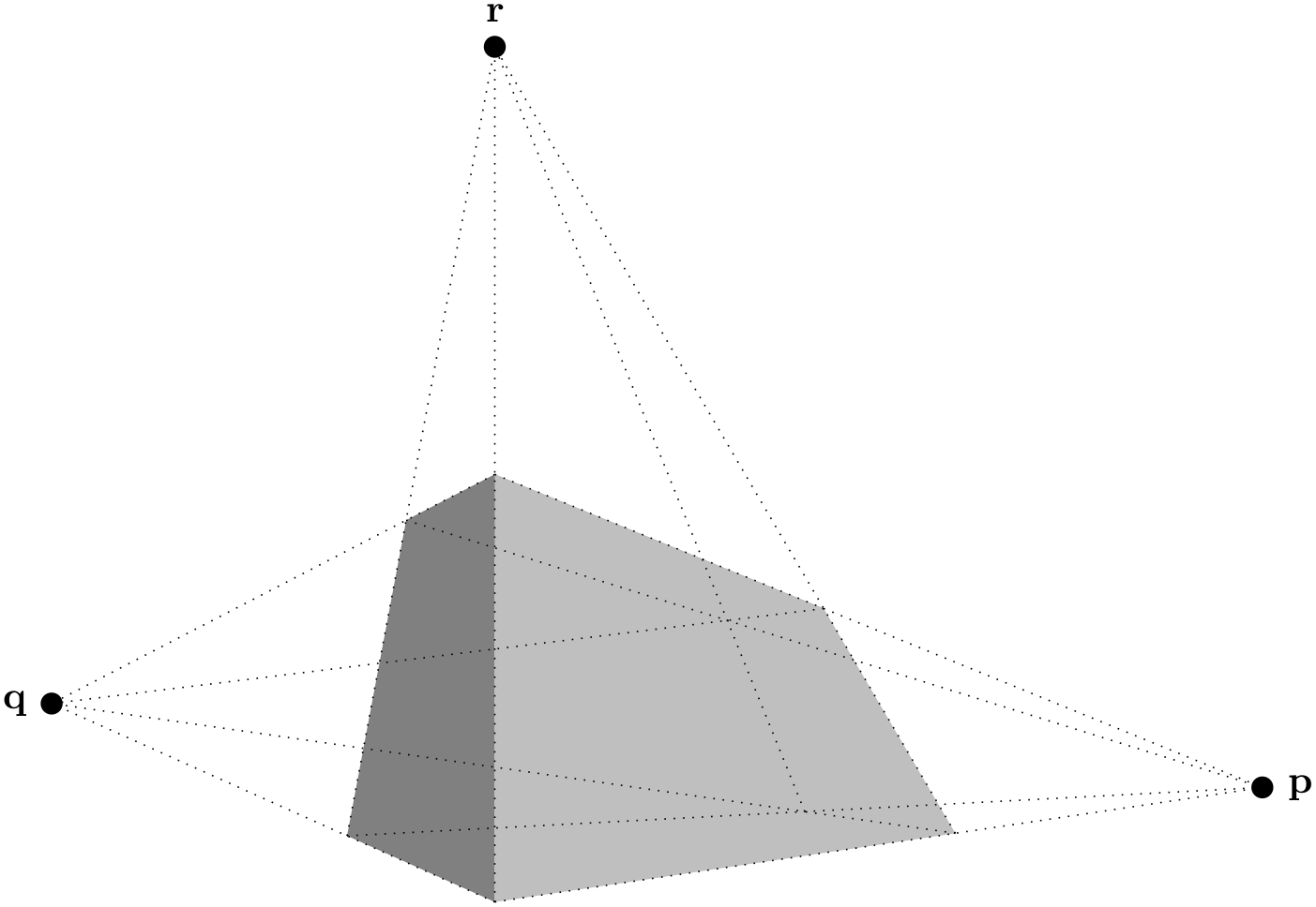
With the vanishing points nearby, the distortion of parallel lines becomes very strong. This might lead to Dimension too large errors.
                \usetikzlibrary {perspective}

                \begin{tikzpicture}[

                  3d view,

                  perspective={

                      p
                  = {(2,0,0)},

                      q
                  = {(0,2,0)},

                      r
                  = {(0,0,2)}},

                  scale=4,

                  vanishing point/.style={fill,circle,inner sep=2pt}]


                  \simplecuboid{3}{1}{2}


                  \node[vanishing point,label =
                right:p] (p) at
                (2,0,0){};

                  \node[vanishing point,label =
                left:q] (q) at
                (0,2,0){};

                  \node[vanishing point,label =
                above:r] (r) at
                (0,0,2){};


                  \begin{scope}[dotted]

                    \foreach \y in
                {0,1}{

                      \foreach \z in
                {0,2}{

                        \draw (tpp cs:x=0,y=\y,z=\z) --
                (p.center);}}

                    \foreach \x in
                {0,3}{

                      \foreach \z in
                {0,2}{

                        \draw (tpp cs:x=\x,y=0,z=\z) --
                (q.center);}}

                    \foreach \x in
                {0,3}{

                      \foreach \y in
                {0,1}{

                        \draw (tpp cs:x=\x,y=\y,z=0) --
                (r.center);}}

                  \end{scope}

                \end{tikzpicture}